When a massive assembly must come together with precision, small misalignments can turn into costly delays fast. Teams that align large parts using a laser tracker need more than measurement alone; they need clear, usable data that supports confident decisions on the floor. A laser tracker helps crews guide adjustments before fit-up issues spread through the rest of the project. In high-stakes environments, that kind of control helps teams protect fit and maintain tolerance.
Large parts create measurement problems that basic hand tools and fixed systems do not handle well across wide working areas. A laser tracker provides teams with a portable way to capture three-dimensional coordinates over long distances by tracking a reflector from point to point.
During alignment, crews can see how a part is positioned, not just whether one isolated dimension looks correct. Real-time feedback helps operators react faster during fit-up, making the tracker especially useful when structures are too large to move easily and when timing matters in complex production environments today.
Preparation shapes the quality of the entire alignment job. Before work begins, the team should define the part coordinate system, confirm which features will control the alignment, and ensure the software file matches the latest build condition. The setup needs stable mounting and a visibly clear work area so the tooling can support repeatable point collection.
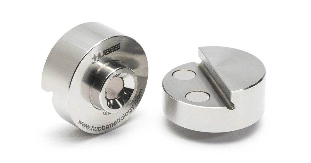
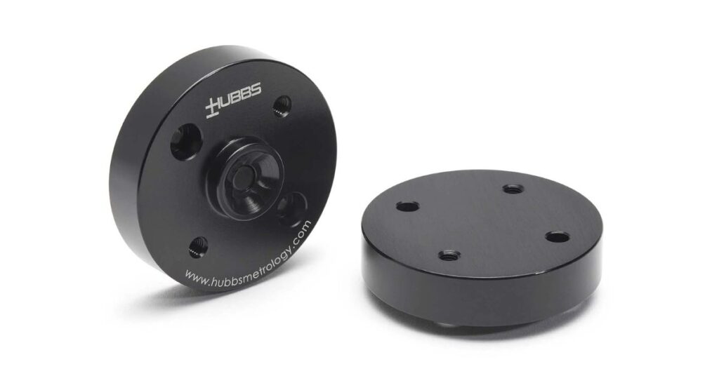
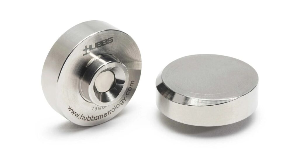
In many applications, .875 SMR mounts help create consistent reflector placement at planned locations. Operators should review access limits, expected obstructions, floor vibration, nearby traffic, reflector reach, and any fixture conditions that could interrupt measurement or slow repositioning once the part starts moving during the job. Preparation prevents confusion once alignment begins.
Alignment works best when every stage has a clear purpose. Each step below moves from preparation into measurement, then correction and confirmation. Following that order helps teams clearly understand what the data means and what action should come next during active work.
Start by placing the tracker where it can see the required work area with as few interruptions as possible. A secure mount matters because setup movement can weaken confidence in later data.
Once the position is chosen, level and initialize the instrument. Then, establish the reference frame the job will use. Good placement reduces relocation and makes the process easier to manage before measurement begins and as crews move safely throughout setup.
The alignment plan needs a nominal reference before measured data can mean anything useful. Import the CAD model or build the required geometry in software so the tracker data has a target condition to compare against.
File control is essential since outdated geometry can lead to wrong correction decisions. Datum features and tooling points should be labeled clearly. A clean digital setup makes later comparisons easier to trust during active alignment work onsite.
After the nominal reference is ready, measure the features that control part location. Focus on target holes, tooling points, mounting faces, or other functional geometry that affects assembly fit.
Point collection should be intentional, as the most useful data comes from locations directly tied to alignment decisions. Measuring the right features keeps the team focused on fit and orientation while consistently collecting only necessary data during each onsite measurement pass.
Measured coordinates become useful when compared with the intended position of the part. Review the deviation results to see whether the issue is a shift in location, a change in angle, or both. Strong comparison work helps crews focus on the problem that matters most first. It also clearly shows where the part differs from the design and how large the mismatch is for the crew in practice.
Use the deviation results to guide controlled part movement. Adjust supports or fixture positions based on the errors that most affect assembly fit. Large components often respond unevenly when one area is moved, so measured feedback matters throughout the correction process.
Crews should make purposeful changes, then remeasure before continuing. Small, informed adjustments create a more stable path toward final alignment on complex assemblies under on-site pressure today and consistently, safely.
Final validation confirms that the corrected position meets job requirements. Return to the controlling features and remeasure them after movement is complete so the team can verify both location and orientation.
Validation should confirm that no shift occurred while clamps were tightened or supports were changed. When the final dataset matches the target condition, the crew has documented proof that alignment was completed properly before release with confidence in the documentation.
Large-part alignment can become more complicated when the challenge comes from job conditions. A laser tracker helps teams work through those issues by showing how the part is behaving as alignment moves forward.
That visibility helps crews make informed corrections and maintain better control over large, complex assemblies.
Some alignment jobs call for more than access to measurement equipment. Large-scale industrial and government applications depend on reliable tooling and products that meet demanding tolerances across complex structures.
HUBBS specializes in precision measurement products for such environments, including laser tracker tooling, photogrammetry contrast products, spherical items, and related accessories for large-scale measurement work.
When teams need to align large parts with a laser tracker, both product quality and measurement consistency matter. HUBBS supports that work with solutions designed for precision-focused applications where confidence in the data plays a role in the outcome. Teams working on demanding projects can turn to HUBBS for precise, repeatable measurement workflows overall.